Simple Remote Control Tester Circuit Diagram


How to Check if a Remote Control is Transmitting an Infrared Signal. Many households have 5 or 6 remote controls laying around the house. This is the simple Remote control tester circuit diagram. When the remote control is not working, first check the battery before, It may be loss.If it is good,so detect transmit infrared light device.However, because the human eye can not see infrared light,so can not know how good or bad.But the photo transistor can use to detect infrared light. 

This circuit so use this photo transistor is the light receiver from the remote control.If it is nice to have the bias current of the transistor BC558.It runs a current flows through the LED,so the LED bright.The remote control that works correctly. The variable resistor VR1 is used to adjust the sensitivity of the circuit.

 Remote control tester circuit diagram
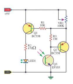
 
 Remote control tester circuit diagram

Comments

Popular posts from this blog

Altec Lansing 353A – power amplifier – vacuum tube type – Circuit diagram 6L6 12AX7

Used tubes – 12AX7 [pre-amplifier, tone control and audio pre-amplifier] – 6L6GC [audio output] Circuit diagram Tube pin-out -6L6 Tube pin-out 12AX7

JCM 800 Emulator Pedal Marshall Amp Simulator

PCB Transfer

NE566 Function Generator Circuit Diagram

The NE566 Function Generator is a Voltage-Controlled Oscillator of exceptional linearity with buf fered square wave and triangle wave outputs. The frequency of oscillation is determined by an external resistor and capacitor and the voltage applied to the control terminal. The Oscillator CAN be programmed over a ten-to-one frequency range by proper selection of an external resistance and modulated over a ten-to-one range by the control voltage, with exceptional linearity.  FMAX = 1 MHz     WIDE 1000:1 Continuous Sweep Possible  NE566 Function Generator Circuit Diagram Pdf Datasheet  Sourced by : Circuitsstream