
SIMPLE LED EMERGENCY LIGHT CIRCUIT


Here i am going to present you a simple Emergency Light circuit diagram using 2 white Leds.

Leds are convenient, cheap, cool and having long life.

In this circuit we are using 2 Leds (white is prefered) to increase the brightness.

The heart of this circuit consists of IC HEF 4093. The circuit is powered by a 9V battery.

CIRCUIT DIAGRAM OF SIMPLE EMERGENCY LAMP/LIGHT


Emergency light circuit diagram


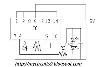
COMPONENTS USED IN THE CIRCUIT

IC HEF 4093

D 1N4001

R1 330KΩ

R2 100Ω

C 10μF


Back To HOME For More


Comments

Popular posts from this blog

Altec Lansing 353A – power amplifier – vacuum tube type – Circuit diagram 6L6 12AX7

Used tubes – 12AX7 [pre-amplifier, tone control and audio pre-amplifier] – 6L6GC [audio output] Circuit diagram Tube pin-out -6L6 Tube pin-out 12AX7

JCM 800 Emulator Pedal Marshall Amp Simulator

PCB Transfer

NE566 Function Generator Circuit Diagram

The NE566 Function Generator is a Voltage-Controlled Oscillator of exceptional linearity with buf fered square wave and triangle wave outputs. The frequency of oscillation is determined by an external resistor and capacitor and the voltage applied to the control terminal. The Oscillator CAN be programmed over a ten-to-one frequency range by proper selection of an external resistance and modulated over a ten-to-one range by the control voltage, with exceptional linearity.  FMAX = 1 MHz     WIDE 1000:1 Continuous Sweep Possible  NE566 Function Generator Circuit Diagram Pdf Datasheet  Sourced by : Circuitsstream