
High Power Amplifier


This circuit of power amplifiers using a booster 8 sets sanken , the buffer using transistor D400 and B560 as much 2 sets , and to use part of the driver transistor B546/A940 and D401/C2168. And least 20 volts and the voltage to 70 volts maximum with three voltage is +,-,ground. Power Output 2 X 600 Watt with 8 Ohm Impedance.
High Power Amplifier
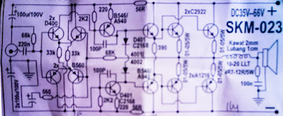
Circuit audio amplifier 600 Watt

High Power Amplifier
Circuit of PCB so from 2  X 600 watts (looked down)

Circuit of PCB (looked upon)

High Power Amplifier
The above is a circuit of ready to operate , just stay put booster.


Source : link

Comments

Popular posts from this blog

TDA2030 complete tone control

At this time I present a series of amplifiers that use IC TDA2030, but this series is equipped with a tone control. Tone controls include Bass, Treebel, and Volume. Power amplifier and tone control has been put together in a single PCB. As well as its power supply circuit was also used as one with the power amp, and tone control. Making it easier in the installation and will look neat. Schematics Layout PCB PCB design This amplifier is a mono amplifier type, can be modif for guitar amplifiers. If not coupled amplifier (mic preamp) then you must deactivated potensio treble and bass, why? because if not using a mic preamp and still maintain potensio treble and bass sound input (input) from the guitar will not or the maximum discharge is not tight on the speakers. So you must deactivated a way to decide which directly connected capacitor with the tone control circuit, and capacitor were connected directly to potensio volume and input jack.

NE566 Function Generator Circuit Diagram

The NE566 Function Generator is a Voltage-Controlled Oscillator of exceptional linearity with buf fered square wave and triangle wave outputs. The frequency of oscillation is determined by an external resistor and capacitor and the voltage applied to the control terminal. The Oscillator CAN be programmed over a ten-to-one frequency range by proper selection of an external resistance and modulated over a ten-to-one range by the control voltage, with exceptional linearity.  FMAX = 1 MHz     WIDE 1000:1 Continuous Sweep Possible  NE566 Function Generator Circuit Diagram Pdf Datasheet  Sourced by : Circuitsstream

PID instruction in Allen Bradley PLC Closed Loop Control

PID instruction in Allen Bradley PLC [Proportional/Integral/Derivative] Closed Loop Control For   Processor SLC 5/02SLC 5/03SLC 5/04SLC 5/05    MicroLogix 1200 and MicroLogix 1500 (A special PID file replaces the old integer file control block.) Description of PID in PLC   This output instruction is used to control physical properties such as temperature, pressure, liquid level, or flow rate of process loops. The PID instruction normally controls a closed loop using inputs from an analog input module and providing an output to an analog output module as a response to effectively hold a process variable at a desired set point. The PID equation controls the process by sending an output signal to the actuator. The greater the error between the setpoint and the process variable input, the greater the output signal, and vice versa. An additional value (feed forward or bias) can be added to the control output as an offset. The result of the PID calculation (control vari...